esp8266-d1-mini-8x-relay-shield-c3
Table of Contents
8x P-channel MOSFET - Wemos D1/S2 mini controlled - Version C3
Inspiration by Everlanders.com Youtube video.
 Q: What is this board good for?
 A: Automotive use - as this board turns power on/off on the plus wire
What is still the same as the Original board:
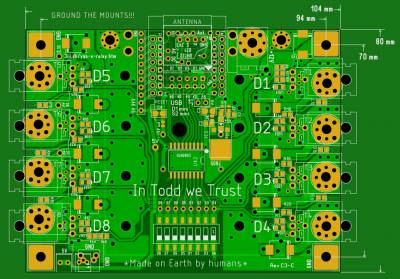
- size of board is exactly the same (80mm x 104mm)
- position of the corner screw holes are exactly the same
- GND is still a part of the corner mounts
- position of (screw holes for) the 8x P-channel MOSFETs are exactly the same
- it is still possible to use the 7805 chip to convert from 12V to 5V (though a DC-DC convert option is added)
- it is still possible to manually activate a MOSFET using a DIP switch
- it is still possible to use the “Wemos D1 mini” as the MCU controller (though a “Wemos S2 mini” is now optional)
- it is still possible to use the very nice 45-degree-angled spring-loaded high-amp Molex connectors
What is changed (or added):
- for low amp boards, 3mm holes to hold the MOSFETs in place has been added
- at the DIP switch, holes have been added (for ease of adding external (miniature relay) control of a channel)
- using 0805 size components (are easier to hand solder)
- because gerber import (to a different design software) was not complete/correct, all copper paths were re-designed (like: GND copper paths are now all connected)
- added IDC 10-pin option (for easy connect/disconnect of RasPi control pins)
- added extra pin rows so the dual rows of the “Wemos S2 mini” (ESP32 27-pin) controller connects to the board
- 8 of the extra S2 pins are available as an 8-pin IO connector
- added an option to use a switch-mode '12V → 5V DC-DC converter' (max 90V or max 28V options)
- added a 5V pin-connector at the bottom edge of the board
- added a GND screw-terminal/connector at the bottom edge of the board
- added solder stripes to the bottom layer - so additional copper strips can be soldered to the board (2x 64amp strips can be added)
- additional power-in connectors/options (blade connectors and/or screw-held ring-eye-lets
- option to use screw-held ring-eye-lets as power-out connectors
- added a DHT22 connection header (S2 mini option on pin D21)
- option for external 12V power-in going to 12V → 5V converter - so a simple on/off signal can remove power from the MCU (and thus can turn the entire board OFF) - in low-battery-voltage situations
- option to dedicate one of the MOSFETs to control the 12V power going to the C3 boards - so a simple on/off signal can remove power from all the MCUs on all the C3 boards (and thus can turn OFF all the C3 boards) - in low-battery-voltage situations
- added a 100nF capacitor to the A0 analog input (might help stabilize the analog reading a little bit)
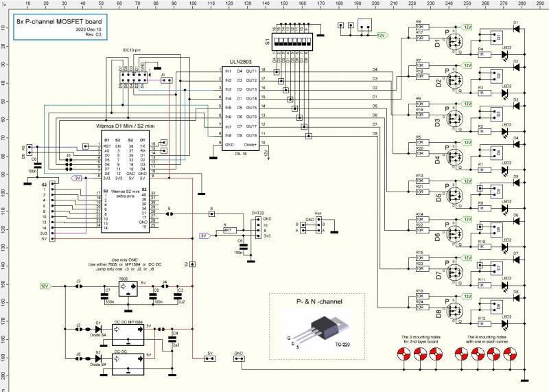
Schematics:
Schematics PDF file: schematics-c3.pdf
PCB Files:
Use the PCB design-file-viewer if you would like to see/test the entire copper path as it switches sides and/or connects to several solder points.
- Link to Free download of the Sprint-layout Viewer program
- The PCB design and gerber files (Status is: PCB UN-tested - ready for PCB test production)
esp8266-d1-mini-8x-relay-shield-c3.txt · Last modified: 2023/12/10 12:01 by mralvin


