Blinky Shield for 'Wemos D1 mini'
This shield adds a LED to every Digital IO-pin of a 'Wemos D1 mini' module
For everything to work well, start the setup() function with a 1-2 milli second (ms) delay.
The reason for this is, that each LED is driven by a separate MOSFET. And the gate pin of each MOSFET is pulled LOW by a 3M3 (3.3 mega ohm) resistor, and after power up, then it takes about 1-2 ms for the state of each pin to settle correctly. This is especially true if the sketch is using the pin for input.
By removing a jumper, it is possible to completely detach the MOSFET (and the pull-down resistor) from each IO pin - if it for any practical reasons becomes necessary
The LEDs for TX and RX pins are reversed, because the resting state of Rx and Tx is HIGH. And thus it is easier to see the blink, if the LED is Off by default, and only is lit up when data is being transmitted.
A p-channel MOSFET is used for Rx and TX pins. A n-channel MOSFET is used for D0-D8 digital pins.
Project Status: PCB design-verify (rev.A1 - 2023 May 26) - getting ready for the June PCB production batch
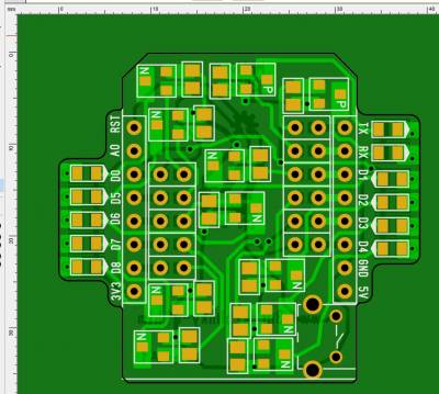
Here are some screen shots:
- TOP side

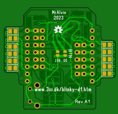
- Bottom Side

Use the PCB viewer if you would like to see/test the entire copper path as it switches sides and/or connects to several solder points.
- Link to Free download of the Sprint-layout Viewer program
- The PCB design file (Status is: PCB UN-tested)
Inspiration - and more Blinky Shields
This Blinky Module is inspired by the 'Maker UNO' board, where LEDs are added to 12 IO pins. See all of the interesting 'Maker Series' of boards.
Sometimes during sketch development, I want some status indication on pins, and I grew tired of using breadboards, wires, LEDs and resistors - so I have now designed this Blinky Shield - this one is for the 'Wemos D1 mini' board.
See also a Blinky Shield for UNO