| First
a few pictures.
The un-touched Fonera
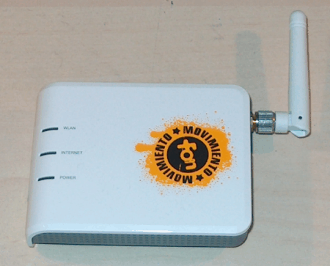
Top view - three LEDs: WLAN, Internet, power.
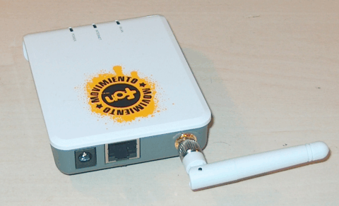
Side view - power socket, Ethernet socket, WiFi antenna
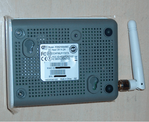
buttom view - you can open the Fonera, by removing two of the
rubber feet, and unscrew the two screws (on the left in the above
picture).
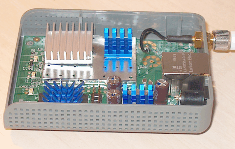
inside view - with a few extra blue heatsinks.
The fonera 2100 originally got quite hot, even
though it had a good size silver-color heatsink attached. It was still
advisable mount it in the upright position and not flat on the back, when
running it for days at a time. Mounted on a "wall" would facilitate
a be better airflow.
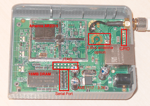
inside view - click image for larger view
- The CPU (top left) Atheros AR2315 is usually
covered by heatsink and hf shield
- 16Mb SDRAM
- Serial port socket/pins
- JTAG sockets
- GPIO - General Purpose I/O sockets
- It is possible to attach an extra antenna, but
it has to be software enabled
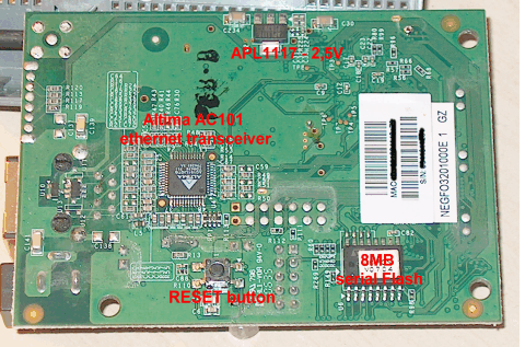
buttom view of circuit board - click image for larger view
- Ethernet tranceiver chip
- 8Mb serial FLASH chip
- Reset Button
I wanted the box to be cool and quiet at all
times, so I added a larger heatsink
I think it is a chopped-up pentium 4 heatsink. Also added the RAM
heatsink.
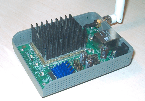
Fonera with additional heatsinks
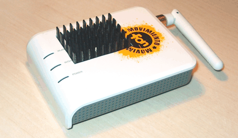
Outside view with the new heatsink.
|