Table of Contents
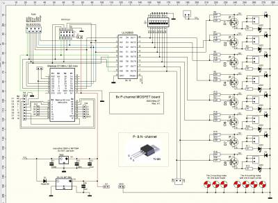
8x P-channel MOSFET - Wemos D1/S2 mini controlled
A work in progress - so far so good  ( contact form )
Project Status: Getting ready for the next PCB batch of PCBs (noted: 2023 July 27 + 2023 Dec 23)
- PCB design-verify (rev.1 - 2023 May 27) - ✔️
- PCB produced - ✔️
- PCB populated - ✔️
- Testing - ✔️ - see more: Rev.1 - Test - observations and conclusions
- A 2nd round of PCBs have been designed,
- and are awaiting the next PCB batch production (noted Dec 3rd)
- (Rev.2 - noted 2023 August 12) - link: 2nd round of base boards
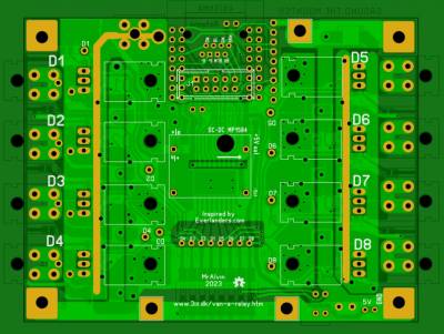
Inspired by Everlanders PCB Design project (video), I have re-visited the 8-port Plus-Side MOSFET board - also lovingly referred to as the 'Todd boards'
So far it has resulted in the design of the following PCBs
- A base board (similar to the Todd boards, but with a few minor additions)
- A piggy-back board (a smaller PCB, to piggy back on the Todd boards - so 16 channels can be managed in the same foot-print area)
- (noted Aug 2023) the piggy-back idea has since been discarded
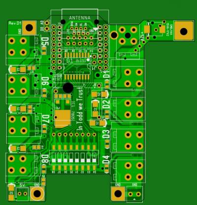
- Added an IDC 10-pin header - Both the Base board and the Piggy-back board have had an IDC-10-pin connector added, so it is easier to wire up the board to be controlled by something else, like a RasPi board
- In addition to the use of the 'Wemos D1 mini' controller, holes have been added, to allow for an option to use the 'Wemos S2 mini' (ESP32) as the controller.
- The 'S2 mini' has 27 IO pins - compared to the 'D1 mini's 9 digital IO pins - so the 'S2 mini' could be used to control as many as three baseboards
or two baseboards and a piggy-back board.
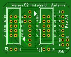
- 3x mini shields with IDC 10-pin connectors, so it is easy to wire up one 'S2 mini' to control up to 3 base boards
- A high amp board (rev.P40-A1). With 6x mosfets in parallel - Likely to be able to handle up to 30-40 amp as is. And with added wires and heat-sink, possibly up 60-80 amps. Once the board have been produced, tests will tell us more about the practical limits
- (test notes August: the 'fake' IRF4905 (with 67mOhm per mosfet) did not deliver the hoped for 30-40Amp ability, so for now this high amp board design test - is on hold)
The Starting Point for a re-visit of the 8x P-channel boards was:
- a 5V pin might have been nice.
- a 10-pin IDC connector might make connecting/disconnecting to the Pi easier
- holes for a screw to hold the TO-220 housing (for the low-power versions), might be handy
- for 24V systems, a DC-DC module, to supply the 5V, might save a Watt a day.
- a solder point for each of the output lines of the ULN2803
- a (smaller) piggy-back board - so up to 16 channels could be controlled from the same footprint-area in the control bay compartment (this was tested - and the idea was discarded)
In the process the following was added
- Wemos S2 mini (ESP32-S2) option was added to the 8x p-channel boards
- A GND screw terminal option (for tests/debug where a GND alu-base-plate is not available).
- A (actually some) max 100×100 mm PCB board design options
- A separate High Amp p-channel board (40-80 amp)
- Miniature Relay shields (for emulating button pushes)
- See also the 'Wemos D1 mini' Miniature Relay Shields
Rev.1 - Test - observations and conclusions
- The MOSFET's (IRF4905) were supposed to be about 20 mΩ - but the first versions I got my hands on turned out to be about 67 mΩ. So they get too hot, too fast. Like burns 1.8W @ 5A (See also spreadsheet images below)
- This lead me to a re-design, where it is possible to have 2-3 mosfets in parallel. Reducing the resistance of the parallelled MOSFET's to about 35 mΩ and about 22 mΩ respectively.
- Alternative sources (more reputable sources) may also be investigated/tested, so the resistance of each MOSFET might get closer to the datasheet specs of 20 mΩ. (This was done in Sept-Nov 2023, so I now have genuine 'less than 20 mΩ' versions in hand - yeah!)
- The piggy-back idea is a no-go. It becomes too difficult to operate the release arms of the power-connectors. Also the tested SO-8-pin MOSFET's (AO4421) get too hot for over 5 Amp loads
For the (new rev.2) boards
- I find it of interest to possibly have some fuses on the PCB - this may be particularly interesting for the low-amp (less than 8-10 amp) boards/ports
- it is possible to use only 1 pin of the 2-pin Power-connectors, for each MOSFET port, as each pin on the Power-connectors are rated for up to 18 Amp. (At max 8-10 amp per mosfet channel, this still keeps the max amp per connector pin, at (or below) 80% of its max ratings).
- using only 4x 2-pin Power-connectors for 8x mosfet ports, allows for on-board (mini) fuses (rev.C4-F).
- (a version with 8x Power-connectors, and 1808 mini fuses (max 15Amp) has also been designed (rev.C44) )
- Spreadsheet of the 67mOhm mosfet observations
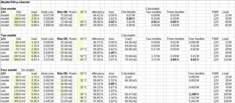
- The spreadsheet: mosfet_8xp-e3.zip

Screenshots
2nd round of Base Boards
Second round of PCBs consists of 4 boards, each with its own set of “power” attributes.
(noted Dec 2023: some of the shown designs have been further developed - pictures may follow in the upcoming weeks (or months) )
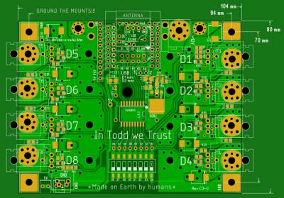
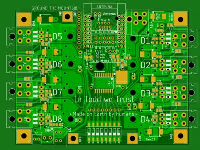
Rev.C3
- same corner-hole position as the Original Todd boards
- Rev.C3 - Top side

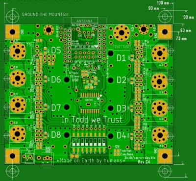
Rev. C4
- Board size 100mm x 83mm - incl. screw holes for holding MOSFETs to an alu-plate - all within the 100mm x 83mm PCB size
- dual MOSFET option for each channel
- 3mm screw option for a high-amp power-in option (so the board can handle up to 80-100 amp total load)
- Option to add copper to buttom traces (so the board can handle up to 80-100 amp total load)
- Added an electronics on/off mosfet control option (so the board can be completely powered off via a low-battery-signal)
- Rev.C4 - Top side

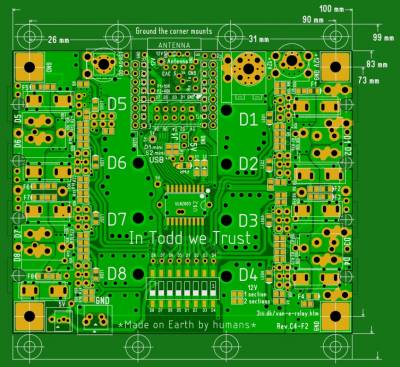
Rev.C4-F
- Board size 100mm x 83mm - incl. screw holes for holding MOSFETs to an alu-plate - all within the 100mm x 83mm PCB size
- dual MOSFET option for each channel
- on-board 1808 fuses for each of the 8 channels
- only 1 power-out-pin for each of the 8 channels
- 3mm screw option for a high-amp power-in option
- Added an electronics on/off mosfet control option (so the board can be completely powered off via a low-battery-signal)
- Rev.C4-F - Top side

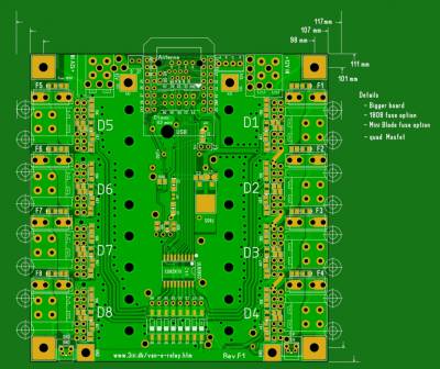
Rev. F1 (primarily experimental - to see how big the PCB 'with it all' might get)
- bigger PCB
- quad-MOSFET option for each channel
- 1808 fuse option, or a 'Mini Blade' fuse option, for each channel
- 2x 2-pin power in connector
- 3mm screw option for a high-amp power-in option
- Rev.F1 - Top side

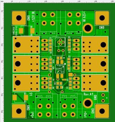
Rev.2 - High Amp board (4x 10-25 amp)
- Top side


1st round of Base Boards
- Top side


- Bottom side

- Schematics:

Use the PCB viewer if you would like to see/test the entire copper path as it switches sides and/or connects to several solder points.
- Link to Free download of the Sprint-layout Viewer program
- The PCB design file (Status is: Rev.C3 PCB - Updated and tested - Noted 2023-08-11)
Piggy-back Board
- Top side

- Bottom side

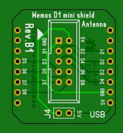
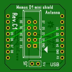
3x IDC 10-pin S2 shields
Main
- Top side

Left
- Top side

Right
- Top side

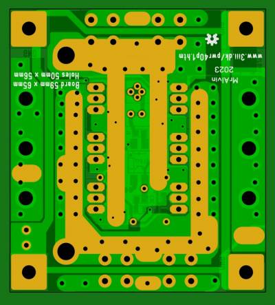
Rev.1 - 30-40 amp power board
Test results (July 2023)
- Actual acquired mosfets (IRF4905) turn out to be about 67 mΩ (and not datasheet spec:20 mΩ) so max Amp (without additional cooling) turns out to be about 15-25 Amp (abt. 6.8W lost in mofets @ 23A load)
- 4x of these boards will/may take up too much space, so a “standard” sized PCB (Todd PCB size) has been re-designed to hold 4x 10-amp-channels and 4x 10-25-amp-channels (even using the 67 mΩ mosfets) (rev.E3).
Design files (May 2023)
- Top side

- Bottom side

Use the PCB viewer if you would like to see/test the entire copper path as it switches sides and/or connects to several solder points.
- Link to Free download of the Sprint-layout Viewer program
- The PCB design file (Status is: PCB UN-tested)
Adding some copper to the PCB
In order to make it easy (and cheap) to add more copper, the bottom side has some exposed copper traces, where 4mm braided copper wire can be soldered on (32 amp wire)
The braided copper wire I have is typically used in connection with 18650 Lithium battery packs. Where higher amp ability than the nickel strips can typically handle, is needed.
The size of the wire is 4mm x 0.7mm = 2.8mm2 (similar to AWG 14-13) so with a recommended limit of about 32 amp
Adding input/output wires
The hole next to the In/Out connectors are 4mm in diameter. So it should be possible to add some 10-8 AWG wires, to test the practical limits of this board.
Connection Options
ToDo